Network Diagram and Rationale (Coursework)
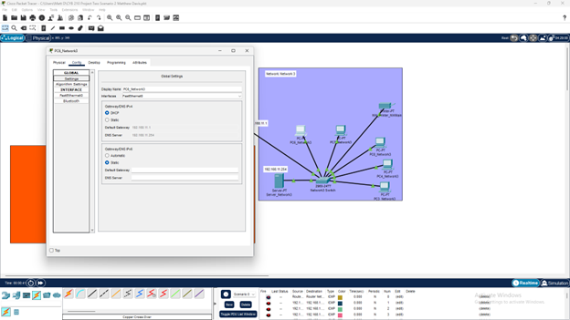
I combined Subnet1 (192.168.1.0) and Subnet2 (192.168.5.0) into a single NetworkA (192.168.1.0/24). I did this by connecting all hosts on one switch and configured a new set of IP addresses for each host on the 192.168.1.0/24 network. The 192.0.0.0 range is a Class C classful range and uses the subnet mask of 255.255.255.0, giving us 256 potential hosts for the network which should be plenty in this scenario with room for future expansion. I was also able to get rid of the switch that Subnet2 was using since all the hosts are connected to a single switch. I also configured a DHCP server for Network3 (192.168.11.0/24) that supplies each host on the network with an IP address automatically via the server. The DHCP service currently has a maximum of 50 hosts, which should be plenty for now. As we add more nodes to Network3 they too will automatically be supplied with an IP address via DHCP, making the setup of additional hosts very simple. Additionally, I added another router to the Network3 infrastructure and added a static route to NetworkA to allow for direct communication between networks. RIP was also updated on each router providing information about the neighboring networks and serial connections. NAT, or Network Address Translation, is used to turn multiple private IP addresses into one when accessing public networks, such as the internet. This helps to reserve public IP addresses and is useful because there is only a limited supply of addresses available for use. This is especially true for IPv4 addresses, which are the current standard. However, as the mass adoption of IPv6 addresses is inevitable, NAT may not be as prominently used in the future
 This was a coursework project
